
A precision casting surface finish that looks smooth may still fall short of a component’s sealing, fatigue, or friction requirements. Investment castings commonly achieve approximately Ra 1.6–6.3 µm, but that range is a planning reference, not a universal process guarantee. Alloy, pattern quality, ceramic shell construction, component geometry, and post-casting treatment all influence the result.
For technical evaluators, the important distinction is between a surface produced by casting and cleaning, and one achieved through controlled material removal. A supplier quoting Ra 1.6 µm may be describing an optimized casting surface, a blasted test area, or a polished production feature. Those are different capabilities—and potentially different costs.
What Ra tells you—and what it leaves out
Ra is the arithmetic mean of the absolute profile deviations from a mean line over the specified evaluation length. It expresses average roughness, usually in micrometres or microinches. A lower value generally indicates a smoother measured profile, but it does not fully describe surface integrity.
Two surfaces with identical Ra can behave differently. One may have closely spaced, shallow irregularities; another may contain isolated deep valleys within an otherwise smooth profile. Their friction, lubricant retention, sealing performance, and fatigue response may differ considerably.
For cast components, separate three questions:
- Texture: Does the measured roughness meet the drawing requirement?
- Discontinuities: Are pits, cracks, inclusions, laps, or exposed porosity acceptable?
- Geometry: Does the surface meet flatness, profile, dimensional tolerance, and other functional requirements?
A low Ra reading cannot establish that a casting is leak-tight, crack-free, or dimensionally correct. Likewise, polishing a surface does not prove that subsurface defects have been removed.
Achievable precision casting surface finish: realistic Ra ranges
Here, “precision casting” refers primarily to lost-wax investment casting. Other processes marketed as precision casting, including permanent-mold and pressure die casting, have different surface-generation mechanisms and should be evaluated separately.
The following ranges are useful for early technical discussions. They are indicative rather than acceptance limits, and they should not replace alloy- and feature-specific supplier data.
For unit comparison, Ra 1.6 µm is approximately 63 µin, Ra 3.2 µm is approximately 126 µin, and Ra 6.3 µm is approximately 248 µin. Drawings often use rounded preferred values, so confirm the governing units rather than converting an acceptance limit informally.
Ra below 1.6 µm should trigger a process discussion, not an automatic rejection. Ask whether the claim applies to an actual production feature, whether finishing is included, and how consistently the supplier achieves it. An external flat pad says little about an inaccessible internal passage.
Where the surface is created—and where control runs out
The pattern and ceramic face coat establish the starting texture
Investment casting reproduces much of the pattern’s surface condition. Wax injection marks, die wear, handling damage, repair areas, and pattern assembly joints can transfer into the ceramic cavity and ultimately into the metal. Improving the ceramic shell cannot reliably compensate for a damaged pattern.
The shell’s primary coat is particularly important because it contacts the molten metal. Refractory particle size, slurry condition, wetting, drying, and coverage influence the resulting texture. A finer face coat can improve reproduction, but it must remain compatible with shell strength, permeability, and casting conditions. “Use finer ceramic” is not a complete process solution.
Alloy chemistry changes the mold–metal interaction
Stainless steels, nickel-based superalloys, aluminum alloys, and titanium alloys do not respond identically to a nominally similar casting route. Pouring temperature, oxidation, fluidity, and chemical interaction with the mold affect surface formation.
Titanium is especially reactive at casting temperatures and requires appropriate mold materials and atmosphere control. Where a reaction-affected layer forms, its removal becomes a surface-integrity issue, not merely a cosmetic roughness adjustment. For aerospace materials, a visually improved surface must still satisfy applicable metallurgical requirements.
Geometry creates local limits
Narrow channels, deep pockets, thin sections, and abrupt transitions complicate mold filling, shell removal, cleaning, and inspection. Internal surfaces may retain ceramic or exhibit localized reaction products that are difficult to remove without changing passage dimensions.
This is why a single whole-part Ra requirement can be misleading. A casting may comfortably meet Ra 3.2 µm on an exposed flange while requiring a different limit or inspection method inside a curved passage.
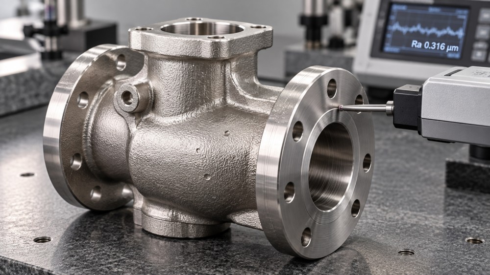
A useful engineering illustration would distinguish the replicated casting texture, an isolated surface pit, and a machined functional land. All three can appear on the same component, but they require different acceptance decisions.
Cleaning, blasting, and polishing are not interchangeable
Foundries must remove the ceramic shell and prepare the casting for inspection. However, the phrase “as-cast finish” is used inconsistently: some suppliers include blasting or pickling, while others distinguish these operations from the casting condition. Define the delivered condition explicitly.
Abrasive blasting removes residue and produces a more uniform appearance, but it does not necessarily lower Ra. Media size, shape, pressure, exposure time, and alloy hardness can create a new texture or alter peaks and valleys. A consistent matte appearance is not proof of improved roughness.
Grinding and machining remove stock predictably when surfaces are accessible and properly located. They are often the practical choice for bearing seats, sealing lands, and precision interfaces. The casting must include sufficient machining allowance; otherwise, cleanup can leave unmachined islands or expose porosity.
Mechanical polishing can reduce roughness substantially, but it may round edges, change local dimensions, or produce uneven removal in recesses. Electropolishing can smooth suitable alloys, although its effectiveness depends on alloy chemistry, initial texture, and current distribution. Neither should be treated as a universal repair for deep pits or casting discontinuities.
For fatigue-sensitive parts, any finishing route also needs consideration of residual stress, surface damage, and contamination. Shot peening, for example, is primarily a controlled surface-enhancement process; its benefit cannot be inferred from a lower Ra value.
Measure the requirement, not just an accessible spot
A roughness number is meaningful only when its measurement conditions are defined. A handheld instrument placed wherever it fits may produce a repeatable reading without representing the critical surface.
For profile-based specifications, use an agreed standard and edition. ISO 21920 addresses profile surface texture in the current ISO framework; legacy drawings may still reference ISO 4287 and ISO 4288. ASME B46.1 is another widely used reference. Do not silently substitute one evaluation framework for another, because filtering, evaluation rules, and specification interpretation can affect acceptance.
The inspection plan should resolve the following details:
- Measurement location: Identify the actual functional zone, not merely a convenient nearby surface.
- Trace direction: Where lay is present, direction affects the result; multidirectional casting textures may require multiple traces.
- Filtering and evaluation length: Select conditions appropriate to the texture, feature size, and governing standard.
- Instrument capability: Stylus tip geometry, access, vibration, and curvature influence contact measurements.
- Sampling: Define locations per part and parts per lot, including how localized unacceptable areas are handled.
Optical methods can help characterize small features or difficult surfaces, but reflectivity, steep slopes, shadowing, and data processing can influence results. An areal parameter such as Sa is not automatically interchangeable with profile Ra. Where different instruments are used by supplier and customer, agree on correlation before production acceptance.
Visual comparators remain useful for screening casting texture and surface discontinuities. ISO 11971 addresses visual examination of steel and iron casting surface quality, but comparator acceptance should not be assumed equivalent to a profilometer Ra requirement.
Specify by function rather than demanding one finish everywhere
Consider an investment-cast valve body. Its external housing, gasket land, threaded connection, and internal flow passage perform different jobs. Assigning Ra 0.8 µm to every surface may add expensive finishing without improving the assembly. Accepting every surface at Ra 6.3 µm may leave the sealing interface unsuitable.
A more defensible drawing separates the requirements:
- General casting surfaces receive an agreed texture requirement and separate discontinuity criteria.
- Sealing lands receive a function-specific roughness limit, geometric controls, and an identified finishing route where necessary.
- Internal passages receive requirements reflecting flow, cleanliness, access, and inspection capability.
- Fatigue-critical transitions receive appropriate surface-integrity controls rather than an Ra limit alone.
For seals, bearing contacts, or lubricated interfaces, additional texture parameters or lay requirements may be necessary. Rz or other profile parameters can complement Ra, but parameter definitions and acceptance rules must remain tied to the specified standard. There is no reliable universal conversion from Ra to Rz.
What evidence should support a supplier’s finish claim?
A photograph and a best-case reading are weak evidence for production capability. Ask for measurements from comparable alloys, geometries, and delivered surface conditions. Results should identify the instrument, measurement settings, locations, finishing sequence, and sample quantity.
When a limit sits near the supplier’s demonstrated capability, request data across multiple parts and production lots. The question is not whether one casting achieved the target, but whether routine variation leaves enough acceptance margin. Capability indices are useful only when the measurement system and statistical assumptions are appropriate.
Clarify rework as well: can the supplier blend a local area, must it be remeasured, and could that operation compromise wall thickness or profile? For aerospace and other controlled applications, verify that finishing, inspection, and process changes follow the applicable customer and quality requirements.
The sound procurement decision is rarely “choose the lowest Ra.” It is to require the surface that the component needs, measure it consistently, and understand the operations needed to deliver it. Treat approximately Ra 1.6–6.3 µm as an investment-casting feasibility window—not a blanket promise—and reserve tighter finishing requirements for surfaces where their functional value is clear.
Related News
- Fatigue Crack Growth in Alloys: How Load Ratio Affects da/dN–ΔK CurvesOct 27, 2026Explore fatigue crack growth alloys exhibit at different load ratios. Learn how closure, thresholds, and da/dN–ΔK curves inform smarter material comparisons and design decisions.
- Surface Engineering: How Coatings and Treatments Reduce Metal WearOct 23, 2026Explore how surface engineering reduces metal wear. Compare coatings, nitriding, and carburizing to choose treatments that improve durability and match real operating conditions.
- Precision Casting Surface Finish: Achievable Ra Values and Process LimitsOct 21, 2026Precision casting surface finish explained: explore achievable Ra values, process limits, and finishing options to specify smarter, control costs, and evaluate supplier claims.
- What Certifications Should EV Aluminum Casting Suppliers Hold?Oct 19, 2026What metallurgy certifications should EV aluminum casting suppliers hold? Explore IATF 16949, ISO 9001, and lab accreditation to verify quality, reduce sourcing risks, and choose with confidence.